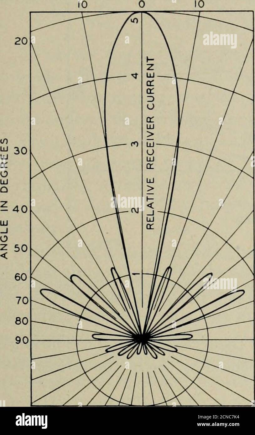
. The Bell System technical journal . Fig. 12—A detail iew of the antenna shown in Fig. 11. HORIZONTAL RHOMBIC ANTENNAS 149 in this manner is shown in Fig. 13. In this figure is also shown, forcomparison purposes, the pattern calculated for these conditions by theequations derived in the appendix. The agreement between these twopatterns is quite evident.. CALCULATED 10 0 10 v--^/ f---,..,, ^ 20 20 / , / T M a. DO 1^ 30 30 -— (^ q: > iij - L/ UJ ict J /^ lU // - // / / 40 40 V--Tr ^ ^ ^^^--^ 90 90 ^^.^ ^^^—■ -^^ 1 m W^ MEASURED 50 Z< Fig. 13—Receiver current diagrams o
Image details
Contributor:
Reading Room 2020 / Alamy Stock PhotoImage ID:
2CNC7K4File size:
7.1 MB (262.1 KB Compressed download)Releases:
Model - no | Property - noDo I need a release?Dimensions:
1251 x 1997 px | 21.2 x 33.8 cm | 8.3 x 13.3 inches | 150dpiMore information:
This image could have imperfections as it’s either historical or reportage.
. The Bell System technical journal . Fig. 12—A detail iew of the antenna shown in Fig. 11. HORIZONTAL RHOMBIC ANTENNAS 149 in this manner is shown in Fig. 13. In this figure is also shown, forcomparison purposes, the pattern calculated for these conditions by theequations derived in the appendix. The agreement between these twopatterns is quite evident.. CALCULATED 10 0 10 v--^/ f~-~--, .., , ____^ 20 20 / , / T M a. DO 1^ 30 30 _-— (^ q: > iij - L/ UJ ict J /^ lU // - // / / 40 40 V--Tr ^ ^ ^^^--^ 90 90 ^^.^ ^^^—■ -^^ 1 m W^ MEASURED 50 Z< Fig. 13—Receiver current diagrams of test antenna output current versus azimuthangle for a 2.7° wave-angle. To check the vertical directivity of the system, a portable oscillatorwas raised from the ground to the top of a one-hundred foot pole infront of the antenna. Due to the limited range of arrival angles soobtained, only the major lobe of the directive pattern could be tracedout. Figure 14 gives the calculated major lobe for these conditions(equations corrected to actual path length difference between direct andreflected waves) with the antenna one-half wave-length above ground, and Fig. 15 is the pattern at a height of one wave-length. The circleson these curves are the