Not done anything PCB related for a while but needed to do this. The 573 wasn't saving settings and so every time I turned it on it was requesting the date settings which was becoming a bit irritating.
The problem lies with a M48T58Y-70PC1 Timekeeper SRAM. The battery in the chip has expired.

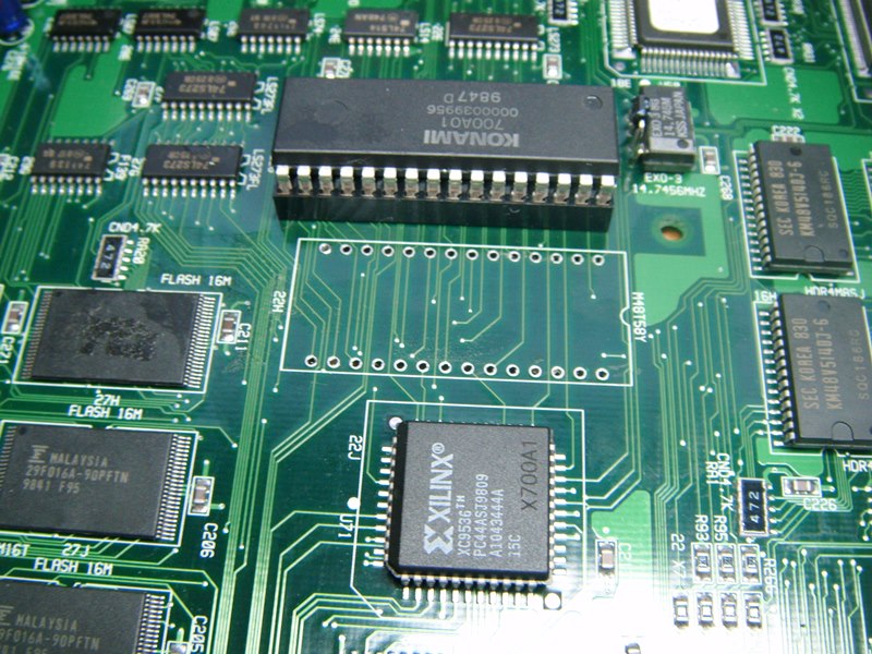
Here is the 573 PCB and the chip in question is under the insulation tape.

Exposed now. The problem with this thing is that it is flush to the PCB meaning access to the pins is only available from the solder side.I prefer to just cut suspect chips out (if they're not customs), happy to destroy them than do anything to the board trying to get them out. Trying to remove chips from certain PCBs can be a problem particularly on multi-layer PCBs - just like this one in fact.

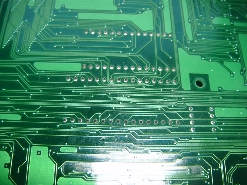
Solder side of the board with 28 pins to de-solder.
I use maximum heat on the iron and use of plenty of flux. I have a solda-pult sucker but using it on this multi-layer is a complete was of time. Prime the pins. Heat the solder and mix with flux. I do this about 5 times. I then use de-solder braid to get remove the solder from the pins. It was a bit touch and go on three pins.

The three pins are numbers pin 26 for some reason and pins 14 & 28 which I assume must be GND and +5V since these were a bitch to clear. The braid causes a little scorching to the PCB but nothing noticeable. I find it the best way for me (on these multi-layer boards).

Here is the chip in question, now out.
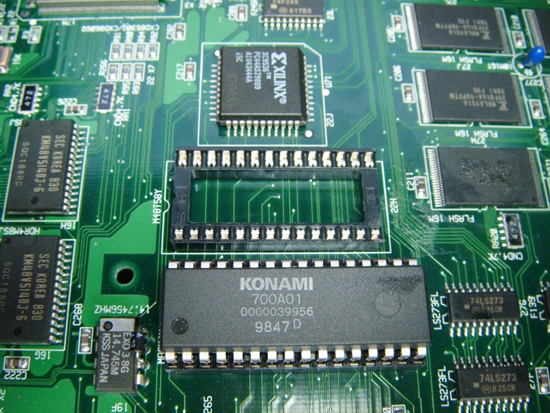
Here is a socket in its place.
It's fairly neat on the solder side.

I've ordered a replacement for the far east for £4 delivered (it's amazing how things can get across the other side of the world for those prices, but I'm not complaining). Put the existing SRAM back in until the replacement arrives. Put everything back together and it's all good.
jonhughes2017-03-03 20:10:31
The problem lies with a M48T58Y-70PC1 Timekeeper SRAM. The battery in the chip has expired.
Here is the 573 PCB and the chip in question is under the insulation tape.
Exposed now. The problem with this thing is that it is flush to the PCB meaning access to the pins is only available from the solder side.I prefer to just cut suspect chips out (if they're not customs), happy to destroy them than do anything to the board trying to get them out. Trying to remove chips from certain PCBs can be a problem particularly on multi-layer PCBs - just like this one in fact.
Solder side of the board with 28 pins to de-solder.
I use maximum heat on the iron and use of plenty of flux. I have a solda-pult sucker but using it on this multi-layer is a complete was of time. Prime the pins. Heat the solder and mix with flux. I do this about 5 times. I then use de-solder braid to get remove the solder from the pins. It was a bit touch and go on three pins.
The three pins are numbers pin 26 for some reason and pins 14 & 28 which I assume must be GND and +5V since these were a bitch to clear. The braid causes a little scorching to the PCB but nothing noticeable. I find it the best way for me (on these multi-layer boards).
Here is the chip in question, now out.
Here is a socket in its place.
It's fairly neat on the solder side.
I've ordered a replacement for the far east for £4 delivered (it's amazing how things can get across the other side of the world for those prices, but I'm not complaining). Put the existing SRAM back in until the replacement arrives. Put everything back together and it's all good.
jonhughes2017-03-03 20:10:31


")