

WARNING!
Before you start:
- I AM NOT RESPONSIBLE FOR ANY DAMAGE TO YOUR Amiga CD32 OR EYES!
- DON’T LOOK INTO THE LASER (BEAM)!! AVOID DIRECT EYE EXPOSURE!!
- ALWAYS COVER THE LASER WHEN TESTING/POWERING THE MACHINE!!
- USE PROTECTIVE GLASSES TO PROTECT YOUR EYES FOR BEING EXPOSED TO THE LASER BEAM!!
- Only continue with the procedures if you know what you are doing!
More information about laser safety: https://en.wikipedia.org/wiki/Laser_safety
The potentiometers
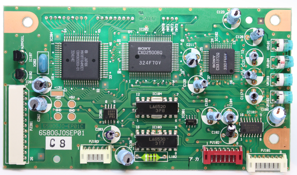
The controller board of the laser unit has four potentiometers:

FEG (VR101 ) – Focus Error Gain
TEG (VR104) – Tracking Error Gain
FEB (VR103) – Focus Error Balance
TEB (VR102) – Tracking Error Balance
Test Points

A: TEO-1
B: FEO-1
C: VF
D: RFO
Before we start
Centre all potentiometers.
Turn all the pots counter clock wise, and then clock wise, now you know the middle point of the pot. Turn each pot to the centre point, it should look like:

Calibrate Focus Error Balance
Before you start be sure there is no CDROM on the player.

Use multimeter to calibrate the Focus Error Balance (FEB), set the multimeter to the millivolt range.
Measure the difference between FEO-1 (B) and VF (C), the voltage level should be under 1 mV.
If you measure the test point FEO-1 voltage on the scope you should have a voltage of +/- 2.5V.
Calibrate Tracking Error Balance
Before you start be sure there is no CDROM on the player.
Use multimeter to calibrate the Tracking Error Balance (TEB), set the multimeter to the millivolt range.
Measure the difference between TEO-1 (A) and VF (C), the voltage level should be under 1 mV.
If you measure the test point TEO-1 (A) voltage on the scope you should have a voltage of +/- 2.5V
Calibrate laser power

Be carefull adjusting this potentiometer, it can damage the laser diode if you apply too much voltage!

To calibrate the laser power you have to use a scope to see the RF signal comming from the laser. Use test point RFO (D) to measure it. To get a good measurement use a silence track.
The voltage levels should be like this:
Original CD: 0.9 Vpp
CD-R: 0.7 Vpp
Don’t exceed 1.2 peak to peak volt !!
Replace laser pickup


If the old laser pickup still suffers problems to read CDROM (Original/CD-R) then consider to replace the laser pickup with a new one.
On Ebay you can find a new one, search for KSS-210A


Replace laser pickup and remove ESD protection
Replacing procedure:
- Remove the old laser pickup
- Place and connect the new laser pickup
- After REPLACING and CONNECTING the new laser pickup remove the ESD protection (solder blob) shown in the left picture
WARNING!! DO NOT REMOVE THIS SOLDER BLOB BEFORE CONNECTING IT! - Perform the calibration process
Here are some pictures to help you a bit to remove the old laser pickup:


RetroGameModz
This knowledge base article is a brief summary of the RetroGameModz video.
https://www.youtube.com/watch?v=lZK3Rmerg1I
Other resources
https://www.repairfaq.org/sam/cdfaq.htm
Thank you Peter MulHolland!