SEGA Game Gear (837-7996) Refurbishment:
I had been looking for a cheap Game Gear to work on for quite a while and after putting feelers out locally I was presented with a broken one that had come out of an attic of a friends acquaintance and asked to give him an offer if I wanted it.
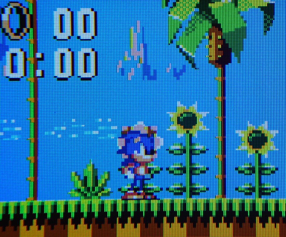
I was allowed to look over it for a few days and found that I could get it to power on for brief periods of time and if I tilted it to very specific angles I could just about make out video albeit with some white horizontal dead pixels in the screen, so I knew a replacement screen would most likely be necessary:
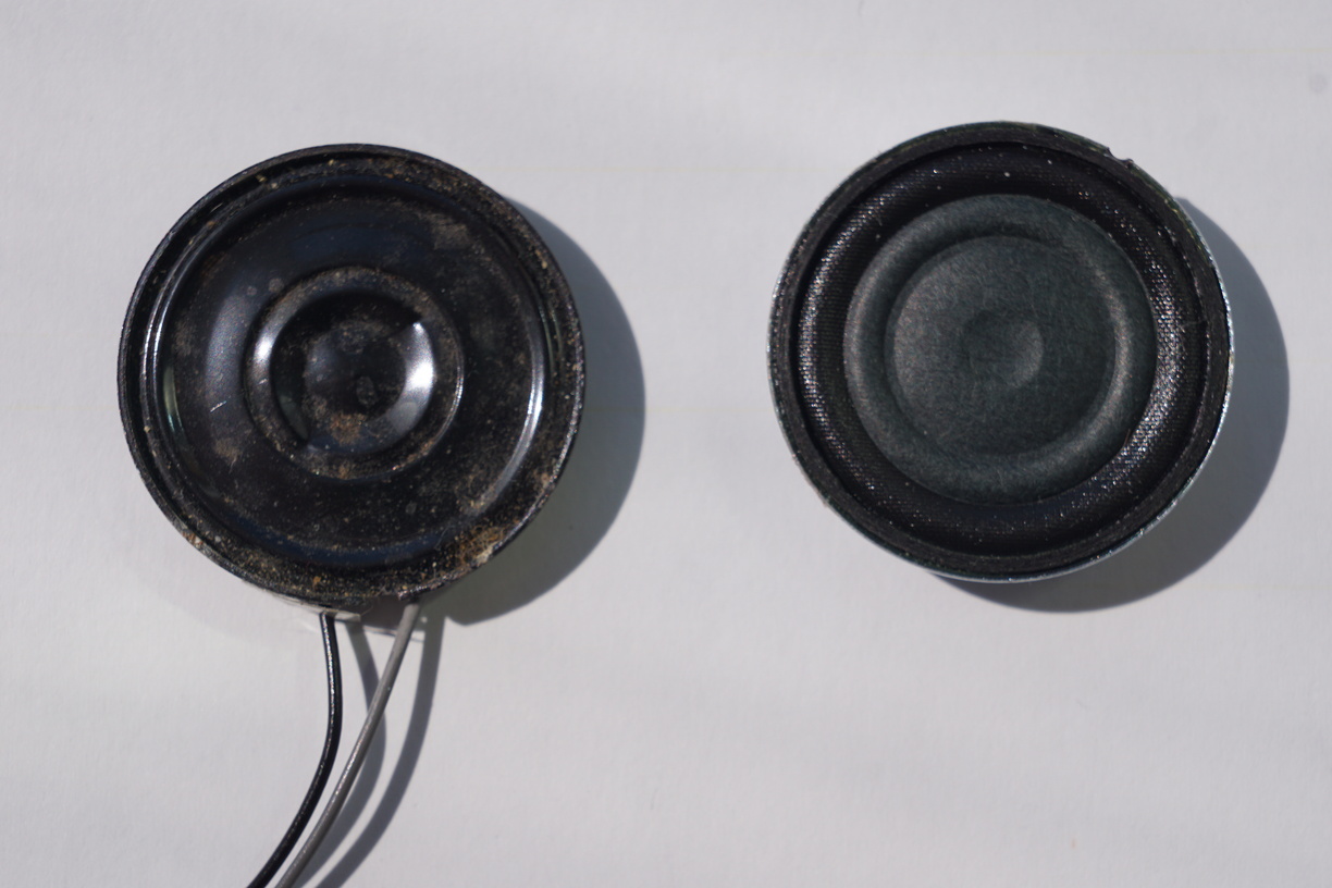
Sadly no sound was coming out of the speaker or the headphone jack, so I opened it up to check on the capacitors and it was obvious they had gone bad and where leaking so I wasn’t too concerned:
The power PCB and the Motherboard PCB didn’t seem to be in too bad shape and hardly any noticeable damage so I decided I wouldn’t mind giving this a go so offered £10 which was eagerly accepted.
Game Gears are notorious for having bad capacitors so a recap was in order.
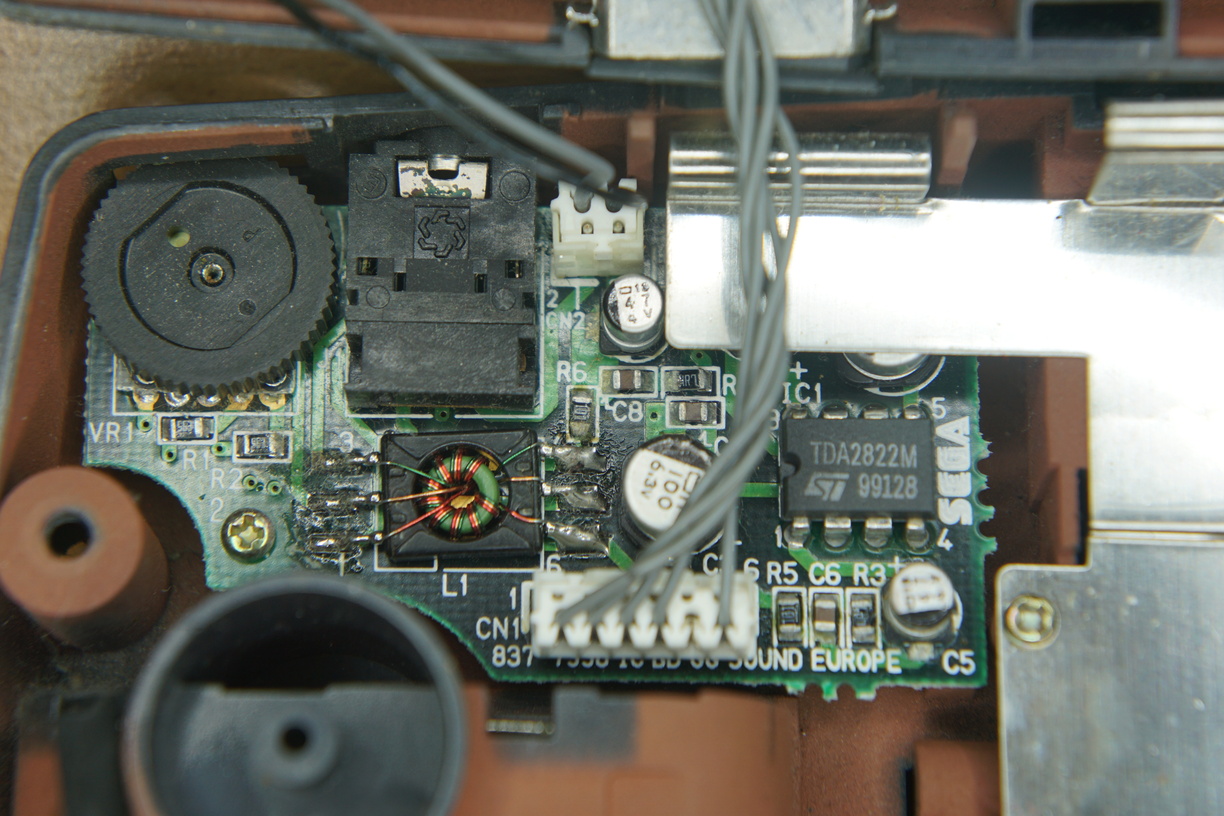
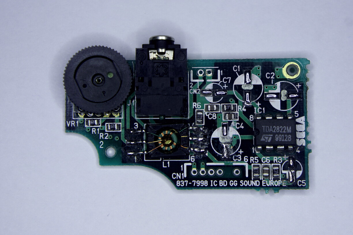
Working on the Audio PCB:
I wanted to ensure that I could get the audio working before I invested too much so I removed the leaking capacitors from the dedicated Audio PCB using a hot air station and then cleaned up the pads:
Unfortunately the positive capacitor leg pad for C3 had lifted due to corrosion, however because the trace itself was not broken I was able to use super glue to tack it back down onto the PCB.
Audio Board Capacitor Summary:
 C1 - 100µf (6.3v) ~ TESTED: 116µf but LEAKING 6.3 (Dia.) x 5.8mm
C2 - 100µf (6.3v) ~ TESTED: 114µf but LEAKING 6.3 (Dia.) x 5.8mm
C3 - 100µf (6.3v) ~ TESTED: 111µf but LEAKING 6.3 (Dia.) x 5.8mm
C5 - 47µf (4v) ~ TESTED: 1.65µf and LEAKING 4 (Dia.) x 5.8mm
C7 - 47µf (4v) ~ TESTED: 0.27µf and LEAKING 4 (Dia.) x 5.8mm
Unlike many other I wanted to replace the capacitors with the same type of SMD capacitors so I had to measure their dimensions and found appropriate Panasonic replacements with part numbers EEEFPJ470UAR & EEEFK1C101P which were soldered in and audio was restored:
POWER PCB
I now removed the capacitors on the dedicated power PCB:
Power Board Capacitor Summary:
 C5 - 22µf (35v) ~ TESTED: 21.18µf
C11 - 100µf (25v) ~ TESTED: 113µf
C13 - 820µf (6.3v) ~ TESTED: 815µf but LEAKING 10 (Dia.) x 12.5mm
I then replaced them with brand new ones:
If after recapping this power board you are still having power issues you should replace the Fujitsu MB3775 IC which is a switching power regulator. However all the voltages were reading fine for me so I did not need to do this, but it is probably recommended if the IC is showing any signs of burn in damage.
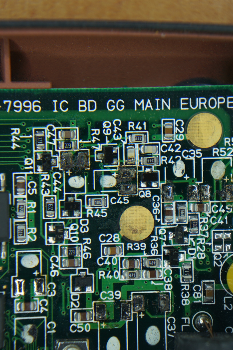
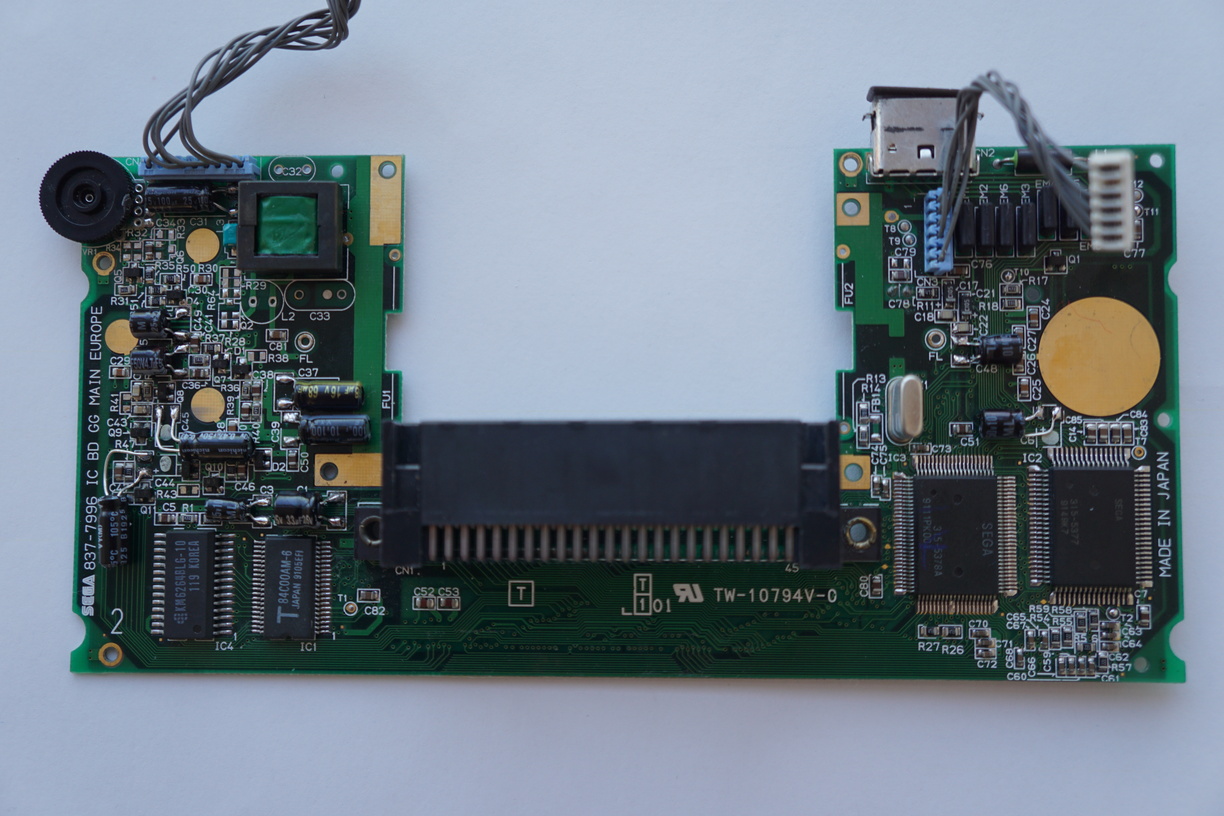
MOTHERBOARD PCB:
While at first glance the capacitors on the main Game Gear board looked to be okay on closer inspection you can see some corrosion on the solder joints:
However once they were removed you could see the damage was much worse:
I had to resort to heavy usage of a fibre glass pen to clean up the pads so they were good enough to re-tin them for the recap. Since the originals are so small it is hard to find replacement electrolytic capacitors that can cleanly replace them:
Due to the clearance available you can take some liberties and use up to 6.3mm diameter capacitors and aim to find 5-6mm length capacitors that can easily fit in the original positions. However for the C44 and C45 0.47µf capacitors I was unable to locate small enough capacitors in stock anywhere so I had to leave the capacitor legs longer to allow me to position them flat in new positions that wouldn’t obstruct the closing of the case:
Also even with a 5mm length capacitor at position C6 it will end up resting on top of the SEGA ASICs so I left the legs longer and bent them to allow a better resting position for it as well:
Motherboard Capacitor Summary:
C1 - 33µf (6.3v) ~ TESTED: 310nf
C3 - 10µf (6.3v) ~ TESTED: 11µf
C6 - 10µf (6.3v) ~ TESTED: 11µf
C31 - 100µf (6.3v) ~ TESTED: 0.03nf and LEAKING
C35 - 4.7µf (35v) ~ TESTED: 1.36 and LEAKING
C37 - 68µf (6.3v) ~ TESTED: 0.03nf
C39 - 100µf (4v) ~ TESTED: 122µf
C44 - 0.47µf (50v) ~ TESTED: 1.15nf and LEAKING
C45 - 0.47µf (50v) ~ TESTED: 71nf and LEAKING
C48 - 10µf (6.3v) ~ TESTED: 8.4µf
C49 - 22µf (6.3v) ~ TESTED: 0.23nf and LEAKING
After I confirmed everything was working after the recap, I used my hot air station on the ribbon cable connecting the original screen to the PCB and removed it along with the CFL back-light and various components that would no longer be required for the replacement screen: