Neural Network Control Design for an Unmanned Aerial Vehicle with a Suspended Payload


1
College of Mechanical and Electronic Engineering, China University of Petroleum (East China), Qingdao 266580, China
2
School of Petroleum Engineering, China University of Petroleum (East China), Qingdao 266580, China
3
Department of Design, Manufacture & Engineering Management, University of Strathclyde, Glasgow G1 1XJ, UK
*
Author to whom correspondence should be addressed.
Electronics 2019, 8(9), 931; https://doi.org/10.3390/electronics8090931
Submission received: 26 July 2019
/
Revised: 15 August 2019
/
Accepted: 22 August 2019
/
Published: 25 August 2019
(This article belongs to the Section Computer Science & Engineering)
Abstract
:Unmanned aerial vehicles (UAVs) demonstrate excellent manoeuvrability in cluttered environments, which makes them a suitable platform as a data collection and parcel delivering system. In this work, the attitude and position control challenges for a drone with a package connected by a wire is analysed. During the delivering task, it is very difficult to eliminate the external unpredictable disturbances. A robust neural network-based backstepping sliding mode control method is designed, which is capable of monitoring the drone’s flight path and desired attitude with a suspended cable attached. The convergence of the position and attitude errors together with the Lyapunov function are employed to attest to the robustness of the nonlinear transportation platform. The proposed control system is tested with a simulation and in an outdoor environment. The simulation and open field test results for the UAV transportation platform verify the controllers’ reliability.
1. Introduction
Drones have aroused great interest in environment monitoring, data collection and device transport [1,2,3]. Because of their capabilities of rapid manoeuvring, great mobility, and precise hovering, unmanned quadrotor helicopters have been deployed for missions in environments unreachable by humans [4,5]. New applications have continuously appeared in recent publications, magazines and newspapers [6,7,8]. Multiple linear and nonlinear control systems have been devised to achieve trajectory planning, obstacle avoidance, UAVs’ cooperation, lifting and landing control [9,10,11]. One of these applications is the UAVs’ aerial transportation systems [12]. They can deliver different equipment and other urgently-needed devices to remote areas. However, in real complex situations, the quadrotor UAVs face many control problems with respect to external disturbances. As shown in [13,14,15], various research works have been conducted on the quadrotor transportation system in the past few years. The typical solution is holding a payload by the actuators with which it is equipped [16,17]. However, this will bring about the slow reaction problem due the inertia added to the UAV. In order to retain the good manoeuvrability of UAVs, another solution is proposed by attaching the payload to the transportation platform via a cable [18,19]. This approach has been widely used in the transfer of radioactive substances or large cargoes [13]. Therefore, the study of quadrotor transportation systems is of theoretical and practical importance. In particular, the robust control of the quadrotor with uncertainties and delays is a critical problem both for the platform and humans on the ground.
Due to the aforementioned reasons, numerous robust control schemes have been developed to address the control challenges of the quadrotor UAVs associated with external uncertainties and disturbances. In [1], a dynamic model of a transportation drone was established, and a nonlinear controller without considering parametric uncertainty was also presented. Seyedtabaii proposed a modified version of Fractional-Order PID (FOPID) in order to reduce the calculations for the uncertainty scenario by replacing the samples’ analytical equation with system frequency response [20]. In [21], a switching model predictive controller was designed to deal with the external disturbances. In [22], the author presented a feedback linearization control approach by considering disturbance from the payload. The phase margin band can be forced to the desired flatness by this proposed method. To maintain the posture-tracking performance against external uncertainties, an theory-based approach was proposed in [23]. In [24], Michailidiset et al. used -synthesis to control UAVs with uncertainties due to its straightforward design. Consideration of the non-linearity of UAVs’ parameters, Mystkowski also proposed to implement the -synthesis method for the UAVs’ dynamics control [25]. In both cases, the lowest output response variance was gained from the -synthesis method. As an alternative method, the sliding model control technique was used in [26] to reduce the parameter variation effect on the control system. Moreover, the quadrotor transportation platform involved time-varying delays. In [27], constant state delays were analysed within the quadrotor helicopter system. The input delays to the system were further discussed in [28]. However, the multiple uncertainties and delays were not considered in the design approach, which will result in an adverse impact on the performance of the transportation system.
In this paper, a Radial Basis Function Neural Network (RBFNN)-based nonlinear backstepping sliding mode flight controller is demonstrated. First, an RBFNN-based approach is employed to deal with the multiple uncertainties and delays. Second, the disturbances in the position and pose control input can be restrained with the modified neural network-based methodology. Third, the stability of the sliding control approach is proven through Lyapunov stability analysis. Finally, the RBFNN-based nonlinear controller is verified via real-time outdoor experiments. The results attest that the performance of the control methodology is able to reject the negative effects of uncertainties and delays.
The main contributions of this paper consist of:
- A 3D dynamic model of a quadrotor transportation system is built.
- The multiple time-varying uncertainties and disturbances are compensated with a novel RBFNN-based backstepping sliding mode control design approach. The stability of the proposed methodology is attested to via analysis of the Lyapunov function.
- The proposed system is tested in a real flight scenario, which validates the robustness of the proposed UAV transportation platform.
The rest of the paper is organized as follows: Section 2 demonstrates the dynamic model of the transportation quadrotor helicopters. In Section 3, we present the RBFNN-based backstepping sliding mode control algorithm and also discuss the stability analysis of the transportation platform. The prototype of the UAV and experimental setup used to evaluate the reliability of the proposed architecture is demonstrated in Section 4. Finally, the conclusion is given in Section 5.
2. Quadrotor Model and Suspended Payload Architecture
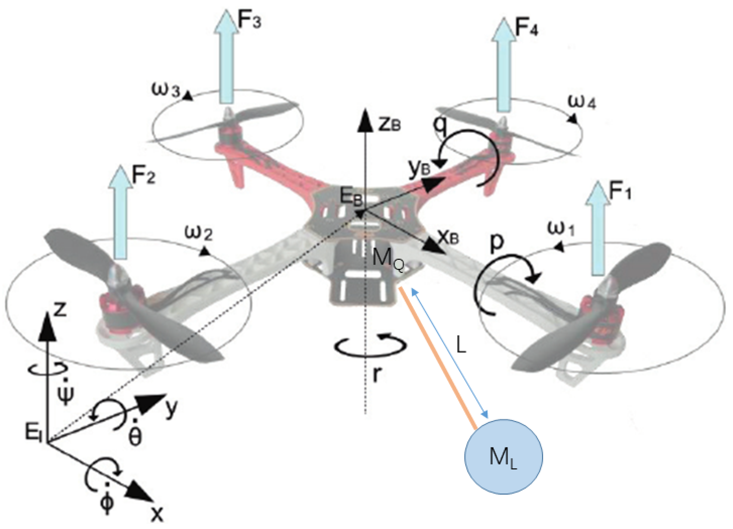
The quadrotor UAV with a suspended payload used in this paper is demonstrated in Figure 1. The structure of this UAV is the “X” type.
The dynamics of the quadrotor without a suspended payload can be expressed with the rotation angle and position data as:
where the Euler angles of the quadrotor are represented as , and . denotes the total thrust as follows:
where k denotes a positive constant and denotes the angular speed, while the attitude inputs (yaw, roll and pitch) are presented by:
where denotes the yaw rotation thrust and and denote the roll and pitch rotation thrust, respectively.
The quadrotor dynamics can be expressed with the rotation angle and position data as [29,30]:
where is the radius of the quadrotor’s arm lever and and represent the body and rotor inertia, respectively.
When adding the payload, the dynamical model can be deduced as [31]:
The dynamic model of quadrotor helicopter in Equation (5) with an external disturbance can be denoted as:
where:
and:
and:
where ; ; ; ; ; ; ; ; ; ; .
3. Neural Network-Based Backstepping Control
The chosen neural network is the RBFNN, which is a three-layer feed-forward network [32,33]. Suppose is an unknown smooth nonlinear function:
where is the optimal weight vector, denotes the radial basis function vector and is the approximation error.
In order to gain the minimum reconstructed error, the can be denoted as:
where represents the estimation of . with nelements in the hidden layer.
Letting be the lumped uncertainty, the output is obtained using the RBFNN weighted sum method as follows:
where denotes the connective weight.
The element of the radial basis function vector is expressed as:
where and are the centre and spread.
The speed and posture control of device transportation is achieved by using backstepping approach [34,35]. Introducing denotes the state vector of the quadrotor helicopter, and is represented in Table 1:
The quadrotor UAV is a highly nonlinear system [36]. The stability of the backstepping controller is attested to via the Lyapunov function [37]. Therefore, an RBFNN-based backstepping control is proposed (as can be seen in Figure 2) to stabilize the quadrotor helicopter during the device transportation missions [38].
The RBFNN-based method is used to overcome the problem of unknown uncertainty. The output in the roll channel is defined as , and the desired output signal of the roll channel is assumed as . Then, the tracking error in the roll channel is denoted as:
The stabilizing function is denoted as:
where represents a positive constant. Denoting the velocity tracking error in the roll channel as , then the first step of the Lyapunov function and its time derivative following Lyapunov theory can be represented as:
The second step of the Lyapunov function is defined as follows [39]:
The sliding mode switching function is denoted as:
where k is a constant and meets the Hurwitz condition, i.e., .
The derivation of can be expressed as:
Following the adaptation approach of the RBFNN observer [40], the error in the roll channel is defined as:
In the actual control, the parameter perturbation and external disturbance are usually unknown, so that the total uncertainty of the upper bound is difficult to determine. Therefore, it is an effective method to estimate the upper bound of the uncertain by using the backstepping control system. The third step Lyapunov function is defined as:
where and denote positive constants. is chosen to compensate the RBFNN observed error, and represents the estimated value of the minimum reconstructed error.
The derivative of is deduced as:
and:
Consequently, the sliding-mode roll control input that is equal to of the transportation platform is designed as:
where and h are positive constants, the robust height control input and a compensated controller are designed as follows:
Accordingly, in Equation (22) can be re-denoted as:
According to Barbalat’s lemma, is secured when is tuned to be positive as:
Therefore, the transportation platform in the roll control input channel is stable despite the presence of time-varying uncertainties.
4. Simulations and Experimental Tests
To assess the performance of the backstepping sliding mode controller, a Hardware-In-The-Loop (HITL) simulation environment was developed for the transportation drone with external disturbance. The structure of the HITL environment is demonstrated in Figure 3. The simulation platform is made up of two main parts: the hardware part and the software part. The hardware part is the Pixhawk autopilot unit that is used in the field tests. The software part is the Gazebo simulation environment running the Ubuntu 18.04 operation system and the Robot Operating System (ROS) Melodic Morenia distribution. The hardware part and software part are connected via USB/UART to send and receive flight data. The RBFNN-based controller was implemented in MATLAB 2018b and PX4 Autopilots Support from Embedded Coder by Simulink.
4.1. Simulation Setup and Results
The reference values for the parameters in the simulation model of the quadrotor are listed in Table 2.
Two simulation tests were carried out to investigate the accuracy and repeatability of the proposed method. The UAV followed the pre-planned trajectory under time-varying wind disturbance. Figure 4 displays the attitude data, roll/pitch/yaw angles and vertical height in the tests.
To achieve the desired control performance, the simulation parameters of RBFNN-based sliding mode control were tuned by trial and error. In addition, the time-varying disturbance, which acts on the attitude control channel, was added by . The other parameters in Equations (27) and (28) were tuned as shown in Table 3.
The structure of the neural network was set to 2-5-1. The centre and width in the hidden node were tuned as = 2 and = 5, respectively. The coefficients and were chosen as nine and two, respectively.
Based on the parameter tuning results, the response speed of the control system, as well as the system stability would be influenced by . In addition, the excessive reduction of k would cause steady-state error to increase. influences the speed of the approach to the sliding surface.
4.2. Field Tests and Results
The performance of the RBFNN-based controller was evaluated via outdoor tests and showed reliable and robust control of the UAV in a cluttered environment.
The characteristics of the UAV are listed as follows:
Autopilot devices: The on-board flight assistant device was a Pixhack-V5 flight autopilot board. The board was based on the Pixhawk open hardware design.
Airframe: The structure of the quadrotor X-shape frame was built using Polyvinyl Chloride (PVC). The main body included motors, Electronics Speed Controller (ESCs)and connection wires.
Attitude and altitude control: The vertical and horizontal position were obtained by using the Auto Control Unit (ACU)and GPS together.
Communication protocol: The communication link used on-board was the Mavlink protocol. The ACU and Operation Unit (OU)used this protocol to send quadrotor helicopter attitude data and control instructions. The drone and GCS were connected via a digital data transmission unit.
Experiment 1: Hovering with external disturbance. In these 20 experiments, we validated the performance of the proposed controller with external disturbance during the hovering, as shown in Figure 5. The Root Mean Squared Error (RMSE) of the distance between the recovery position after the disturbance injection and the quadrotor’s original position is shown in Table 4.
Forty real tests using the quadrotor transportation platform were carried out in an open field. The transportation system was tested on days with wind speeds below 15 m/s.
In these experiments, as shown in Figure 6 and Figure 7, the attitude angles recovered to their desired values within 2 s. The experimental results directly proved that the proposed control scheme would be safe during the payload changing and sample taking process.
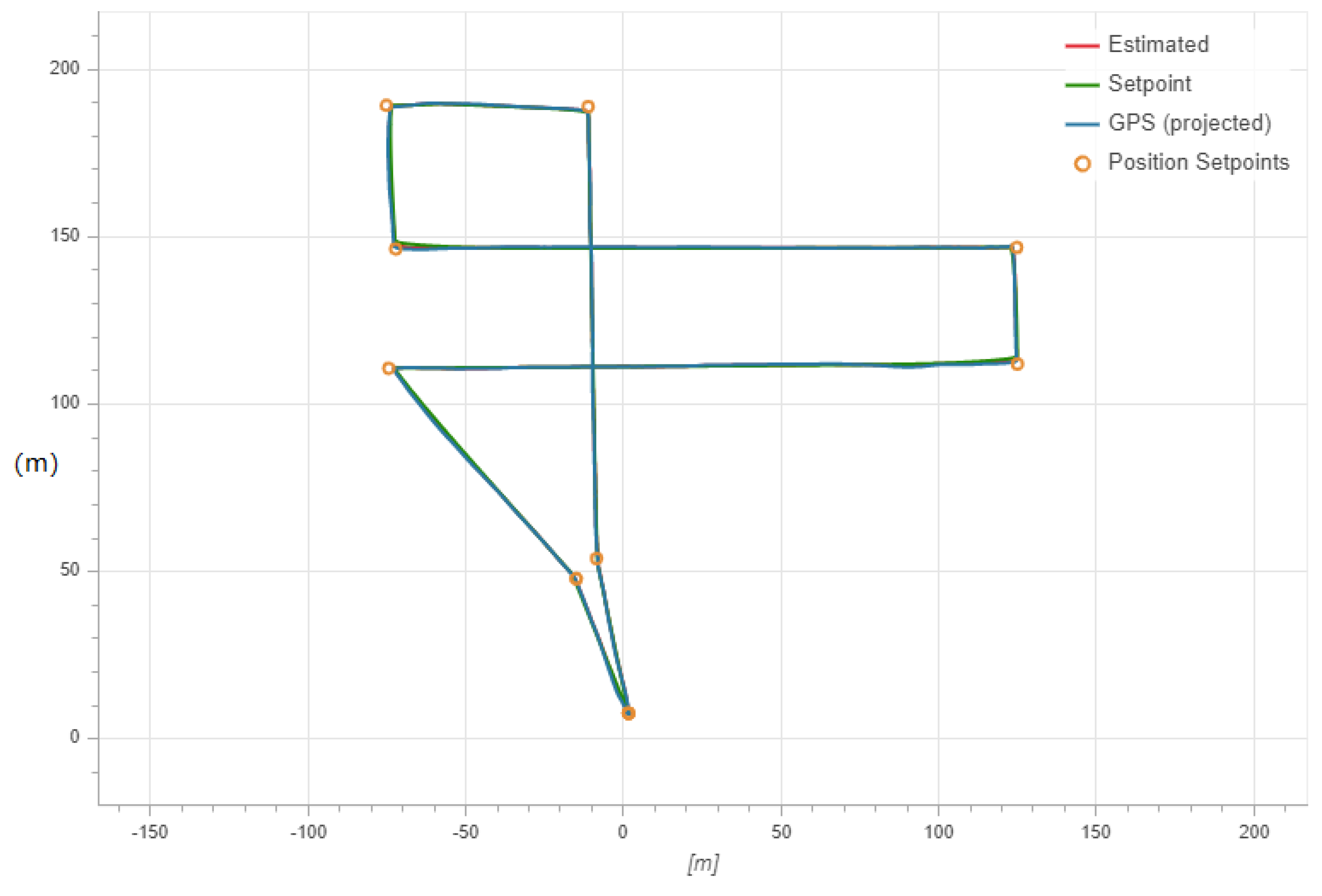
Experiment 2: Path following with wind disturbance. We set up 20 sample transport tests in an outdoor flight field, as can be seen in Figure 8. The wind speed was between 2 m/s and 15 m/s during the tests. The path setting is shown in Figure 9.
Videos of the aforementioned experiments are available at the following websites:
- Hovering with external disturbance: https://youtu.be/MZfE9BsYLqY.
- Path following with wind disturbance: https://youtu.be/ENtDYhLWR5Y.
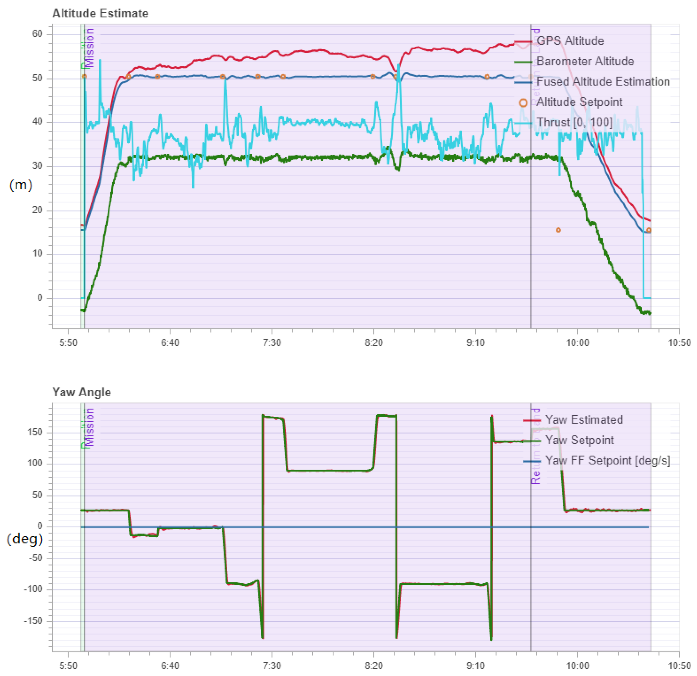
In these 20 transporting experiments, the UAV was capable of following the desired path during uncertain wind disturbance. Figure 10 displays the altitude estimation, yaw angle, pitch angle, roll angle and velocity over time in the transporting process. As demonstrated, the proposed controller was fully capable of maintaining the altitude and attitude of the quadrotor when encountering uncertain disturbances.
5. Conclusions
An RBFNN-based backstepping sliding mode control scheme was proposed for a UAV transportation system, which could effectively suppress the uncertain external disturbances and secure accurate quadrotor positioning. The lumped external disturbances could be estimated with the support of the adaptive RBFNN observer. In particular, Lyapunov-based analysis was employed to theoretically ensure the performance of the neural network control scheme.
The proposed RBFNN-based backstepping sliding mode control method was verified through numerous simulations, where constant external disturbance and time-varying disturbance were taken into account. Experimental results were also included to show the proposed method’s superior control performance.
Author Contributions
Conceptualization, C.L.; formal analysis, C.L. and L.Y.; funding acquisition, C.L.; software, Z.D.; visualization, Z.D.; writing, original draft, C.L. and L.Y.; writing, review and editing, C.L.
Funding
The work was supported in part by the Fundamental Research Funds for the Central Universities under Grant 19CX02021A.
Conflicts of Interest
The authors declare no conflict of interest.
References
- Liang, X.; Fang, Y.; Sun, N.; Lin, H. Nonlinear hierarchical control for unmanned quadrotor transportation systems. IEEE Trans. Ind. Electron. 2017, 65, 3395–3405. [Google Scholar] [CrossRef]
- Palunko, I.; Cruz, P.; Fierro, R. Agile load transportation: Safe and efficient load manipulation with aerial robots. IEEE Robot. Autom. Mag. 2012, 19, 69–79. [Google Scholar] [CrossRef]
- Valente, J.; Sanz, D.; Barrientos, A.; Cerro, J.D.; Ribeiro, Á.; Rossi, C. An air-ground wireless sensor network for crop monitoring. Sensors 2011, 11, 6088–6108. [Google Scholar] [CrossRef]
- Li, B.; Zhou, W.; Sun, J.; Wen, C.Y.; Chen, C.K. Development of model predictive controller for a Tail-Sitter VTOL UAV in hover flight. Sensors 2018, 18, 2859. [Google Scholar] [CrossRef] [PubMed]
- Luque-Vega, L.F.; Castillo-Toledo, B.; Loukianov, A.; Gonzalez-Jimenez, L.E. Power line inspection via an unmanned aerial system based on the quadrotor helicopter. In Proceedings of the MELECON 2014—2014 17th IEEE Mediterranean Electrotechnical Conference, Beirut, Lebanon, 13–16 April 2014; pp. 393–397. [Google Scholar]
- Pastor, E.; Lopez, J.; Royo, P. UAV payload and mission control hardware/software architecture. IEEE Aerosp. Electron. Syst. Mag. 2007, 22, 3–8. [Google Scholar] [CrossRef]
- Goodarzi, F.A.; Lee, D.; Lee, T. Geometric control of a quadrotor UAV transporting a payload connected via flexible cable. Int. J. Control Autom. Syst. 2015, 13, 1486–1498. [Google Scholar] [CrossRef] [Green Version]
- Liang, X.; Fang, Y.; Sun, N.; Lin, H. Dynamics analysis and time-optimal motion planning for unmanned quadrotor transportation systems. Mechatronics 2018, 50, 16–29. [Google Scholar] [CrossRef]
- Richter, C.; Bry, A.; Roy, N. Polynomial trajectory planning for aggressive quadrotor flight in dense indoor environments. In Robotics Research; Springer: Berlin, Germany, 2016; pp. 649–666. [Google Scholar]
- Allen, R.; Pavone, M. A real-time framework for kinodynamic planning with application to quadrotor obstacle avoidance. In Proceedings of the AIAA Guidance, Navigation, and Control Conference, San Diego, CA, USA, 4–8 January 2016; p. 1374. [Google Scholar]
- Polvara, R.; Patacchiola, M.; Sharma, S.; Wan, J.; Manning, A.; Sutton, R.; Cangelosi, A. Autonomous quadrotor landing using deep reinforcement learning. arXiv 2017, arXiv:1709.03339. [Google Scholar]
- Estevez, J.; Lopez-Guede, J.M.; Graña, M. Particle swarm optimization quadrotor control for cooperative aerial transportation of deformable linear objects. Cybern. Syst. 2016, 47, 4–16. [Google Scholar] [CrossRef]
- Faust, A.; Palunko, I.; Cruz, P.; Fierro, R.; Tapia, L. Automated aerial suspended cargo delivery through reinforcement learning. Artif. Intell. 2017, 247, 381–398. [Google Scholar] [CrossRef] [Green Version]
- Klausen, K.; Fossen, T.I.; Johansen, T.A. Nonlinear control of a multirotor UAV with suspended load. In Proceedings of the 2015 International Conference on Unmanned Aircraft Systems (ICUAS), Denver, CO, USA, 9–12 June 2015; pp. 176–184. [Google Scholar]
- Sreenath, K.; Michael, N.; Kumar, V. Trajectory generation and control of a quadrotor with a cable-suspended load-a differentially-flat hybrid system. In Proceedings of the 2013 IEEE International Conference on Robotics and Automation, Karlsruhe, Germany, 6–10 May 2013; pp. 4888–4895. [Google Scholar]
- Masone, C.; Bülthoff, H.H.; Stegagno, P. Cooperative transportation of a payload using quadrotors: A reconfigurable cable-driven parallel robot. In Proceedings of the 2016 IEEE/RSJ International Conference on Intelligent Robots and Systems (IROS), Daejeon, Korea, 9–14 October 2016; pp. 1623–1630. [Google Scholar]
- Estevez, J.; Lopez-Guede, J.M.; Grana, M. Quasi-stationary state transportation of a hose with quadrotors. Robot. Auton. Syst. 2015, 63, 187–194. [Google Scholar] [CrossRef]
- Foehn, P.; Falanga, D.; Kuppuswamy, N.; Tedrake, R.; Scaramuzza, D. Fast Trajectory Optimization for Agile Quadrotor Maneuvers with a Cable-Suspended Payload. In Proceedings of the Robotics: Science and Systems, Cambridge, MA, USA, 12–16 July 2017; pp. 1–10. [Google Scholar]
- Gassner, M.; Cieslewski, T.; Scaramuzza, D. Dynamic collaboration without communication: Vision-based cable-suspended load transport with two quadrotors. In Proceedings of the 2017 IEEE International Conference on Robotics and Automation (ICRA), Singapore, 29 May–3 June 2017; pp. 5196–5202. [Google Scholar]
- Seyedtabaii, S. A Modified FOPID Versus H∞ and μ Synthesis Controllers: Robustness Study. Int. J. Control Autom. Syst. 2019, 17, 639–646. [Google Scholar] [CrossRef]
- Qian, L.; Liu, H.H. Path Following Control of A Quadrotor UAV with A Cable Suspended Payload Under Wind Disturbances. IEEE Trans. Ind. Electron. 2019. [Google Scholar] [CrossRef]
- Alexis, K.; Nikolakopoulos, G.; Tzes, A. Switching model predictive attitude control for a quadrotor helicopter subject to atmospheric disturbances. Control Eng. Pract. 2011, 19, 1195–1207. [Google Scholar] [CrossRef] [Green Version]
- Wang, L.; Su, J. Robust disturbance rejection control for attitude tracking of an aircraft. IEEE Trans. Control Syst. Technol. 2015, 23, 2361–2368. [Google Scholar] [CrossRef]
- Michailidis, M.G.; Kanistras, K.; Agha, M.; Rutherford, M.J.; Valavanis, K.P. Nonlinear Control of Fixed-Wing UAVs with Time-Varying Aerodynamic Uncertainties Via μ-Synthesis. In Proceedings of the 2018 IEEE Conference on Decision and Control (CDC), Miami Beach, FL, USA, 17–19 December 2018; pp. 6314–6321. [Google Scholar]
- Mystkowski, A. Implementation and investigation of a robust control algorithm for an unmanned micro-aerial vehicle. Robot. Auton. Syst. 2014, 62, 1187–1196. [Google Scholar] [CrossRef]
- Benallegue, A.; Mokhtari, A.; Fridman, L. High-order sliding-mode observer for a quadrotor UAV. Int. J. Robust Nonlinear Control IFAC Affil. J. 2008, 18, 427–440. [Google Scholar] [CrossRef]
- Ordaz, J.; Salazar, S.; Mondié, S.; Romero, H.; Lozano, R. Predictor-based position control of a quad-rotor with delays in GPS and vision measurements. J. Intell. Robot. Syst. 2013, 70, 13–26. [Google Scholar] [CrossRef]
- Wang, Q.; Wang, J.W.; Yu, Y.; Sun, C.Y. Robust attitude control of an indoor micro quadrotor with input delay. In Proceedings of the 2014 IEEE Chinese Guidance, Navigation and Control Conference, Yantai, China, 8–10 August 2014; pp. 2363–2368. [Google Scholar]
- Luo, C.; Yu, L.; Ren, P. A vision-aided approach to perching a bioinspired unmanned aerial vehicle. IEEE Trans. Ind. Electron. 2017, 65, 3976–3984. [Google Scholar] [CrossRef]
- Bouabdallah, S.; Siegwart, R. Full control of a quadrotor. In Proceedings of the 2007 IEEE/RSJ International Conference on Intelligent Robots and Systems, San Diego, CA, USA, 29 October–2 November 2007; pp. 153–158. [Google Scholar]
- Hwangbo, J.; Sa, I.; Siegwart, R.; Hutter, M. Control of a quadrotor with reinforcement learning. IEEE Robot. Autom. Lett. 2017, 2, 2096–2103. [Google Scholar] [CrossRef]
- Pedrycz, W. Conditional fuzzy clustering in the design of radial basis function neural networks. IEEE Trans. Neural Netw. 1998, 9, 601–612. [Google Scholar] [CrossRef] [PubMed]
- Ghosh-Dastidar, S.; Adeli, H.; Dadmehr, N. Principal component analysis-enhanced cosine radial basis function neural network for robust epilepsy and seizure detection. IEEE Trans. Biomed. Eng. 2008, 55, 512–518. [Google Scholar] [CrossRef] [PubMed]
- Mohd Basri, M.A.; Husain, A.R.; Danapalasingam, K.A. Intelligent adaptive backstepping control for MIMO uncertain non-linear quadrotor helicopter systems. Trans. Inst. Meas. Control 2015, 37, 345–361. [Google Scholar] [CrossRef]
- Zou, Y.; Zheng, Z. A robust adaptive RBFNN augmenting backstepping control approach for a model-scaled helicopter. IEEE Trans. Control Syst. Technol. 2015, 23, 2344–2352. [Google Scholar] [CrossRef]
- Voos, H. Nonlinear control of a quadrotor micro-UAV using feedback-linearization. In Proceedings of the 2009 IEEE International Conference on Mechatronics, Malaga, Spain, 14–17 April 2009; pp. 1–6. [Google Scholar]
- Cichella, V.; Kaminer, I.; Xargay, E.; Dobrokhodov, V.; Hovakimyan, N.; Aguiar, A.P.; Pascoal, A.M. A Lyapunov-based approach for time-coordinated 3D path-following of multiple quadrotors. In Proceedings of the 2012 IEEE 51st IEEE Conference on Decision and Control (CDC), Maui, HI, USA, 10–13 December 2012; pp. 1776–1781. [Google Scholar]
- Chen, F.; Jiang, R.; Zhang, K.; Jiang, B.; Tao, G. Robust backstepping sliding-mode control and observer-based fault estimation for a quadrotor UAV. IEEE Trans. Ind. Electron. 2016, 63, 5044–5056. [Google Scholar] [CrossRef]
- Powers, C.; Mellinger, D.; Kumar, V. Quadrotor kinematics and dynamics. In Handbook of Unmanned Aerial Vehicles; Springer: Berlin, Germany, 2015; pp. 307–328. [Google Scholar]
- Faessler, M.; Fontana, F.; Forster, C.; Mueggler, E.; Pizzoli, M.; Scaramuzza, D. Autonomous, vision-based flight and live dense 3D mapping with a quadrotor micro aerial vehicle. J. Field Robot. 2016, 33, 431–450. [Google Scholar] [CrossRef]
Figure 1.
The “X” type of quadrotor helicopters.

Figure 2.
Blockdiagram of the neural network-based backstepping control.

Figure 3.
Block diagram of the hardware-in-the-loop simulation environment.

Figure 4.
Altitude and attitude variation of the quadrotor during the simulation of the transportation platform.
Figure 4.
Altitude and attitude variation of the quadrotor during the simulation of the transportation platform.

Figure 5.
UAV transportation system used in the field tests.

Figure 6.
Altitude and attitude variation of the quadrotor during the hovering field tests.

Figure 7.
Uncertain disturbances were injected during the hovering tests.

Figure 8.
The UAV transportation system following the pre-planned path in the outdoor experiments.

Figure 9.
The pre-planned path for the transportation tests.

Figure 10.
Altitude and attitude variation of the quadrotor during the hovering field tests.


Table 1.
State vector of the quadrotor helicopter platform.
| Notation | ||||||
|---|---|---|---|---|---|---|
| State | z | y | x |
Table 2.
State vector of the quadrotor helicopter platform.
| Parameter | Value |
|---|---|
| Mass (kg) | 0.23 |
| Arm length (m) | 0.45 |
| k | 0.0000326 |
| b | 0.000021 |
| J | diag (0.0001612, 0.0001288, 0.0002225) |
| Attitude Channel | k | h | ||
|---|---|---|---|---|
| Roll | 10 | 0.5 | 15 | 1 |
| Pitch | 15 | 0.5 | 25 | 4 |
| Yaw | 12 | 0.5 | 20 | 1 |
Table 4.
Hovering performance error.
| RMSE Horizontal X,Y (m) | 0.021 |
| RMSE Vertical Z (m) | 0.082 |
© 2019 by the authors. Licensee MDPI, Basel, Switzerland. This article is an open access article distributed under the terms and conditions of the Creative Commons Attribution (CC BY) license (http://creativecommons.org/licenses/by/4.0/).
Share and Cite
MDPI and ACS Style
Luo, C.; Du, Z.; Yu, L. Neural Network Control Design for an Unmanned Aerial Vehicle with a Suspended Payload. Electronics 2019, 8, 931. https://doi.org/10.3390/electronics8090931
AMA Style
Luo C, Du Z, Yu L. Neural Network Control Design for an Unmanned Aerial Vehicle with a Suspended Payload. Electronics. 2019; 8(9):931. https://doi.org/10.3390/electronics8090931
Chicago/Turabian StyleLuo, Cai, Zhenpeng Du, and Leijian Yu. 2019. "Neural Network Control Design for an Unmanned Aerial Vehicle with a Suspended Payload" Electronics 8, no. 9: 931. https://doi.org/10.3390/electronics8090931
Note that from the first issue of 2016, this journal uses article numbers instead of page numbers. See further details here.