Pictorial Review of Gamma Match Implementation
Pictorial Review of Gamma Match Implementation
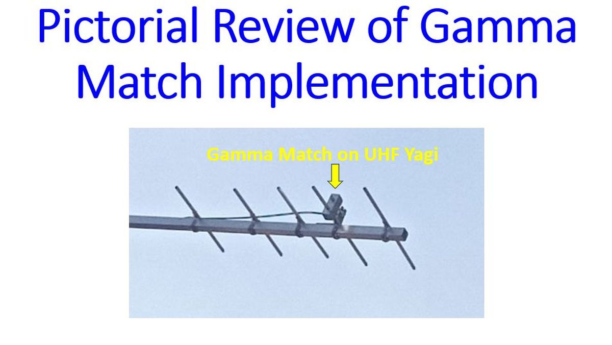
Here is the gamma match on my 5 element UHF Yagi antenna. This pictorial review is complementary to
my previous post on gamma match, regarding implementation for Yagi antennas.
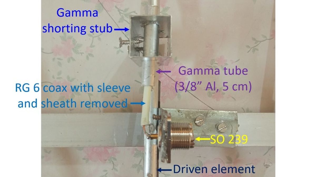
Closeup view of the gamma match assembly on the UHF Yagi, showing the gamma shorting stub, gamma tube, RG 6 coax with sleave and sheath removed and the connection to SO 239 fixed on the boom near the driven element. Gamma shorting stub can be moved over the gamma tube and driven element, millimeter by millimeter, checking the SWR, for tuning the Yagi antenna for minimum SWR. When the best SWR is obtained, the screws on the shorting stub can be tightened further to prevent inadvertent movements. SWR is rechecked once again for confirmation. Adjusting the gamma match is in effect tuning a variable capacitor formed by the combination of coax inner conductor with dielectric covering
and the gamma tube surrounding it.
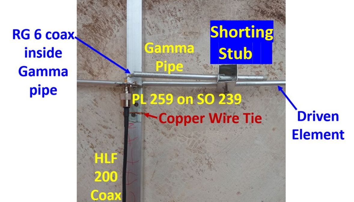
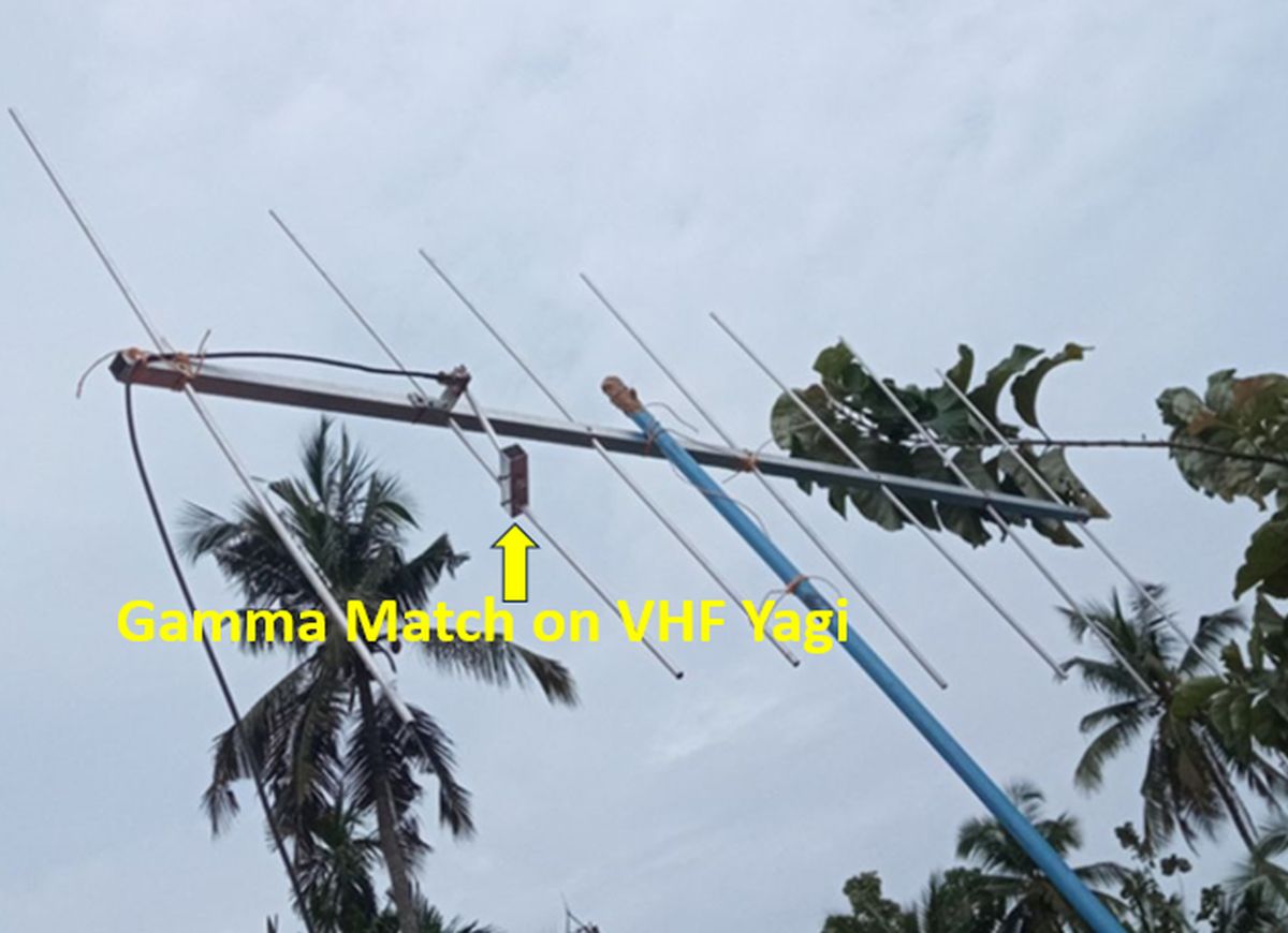
Here is a picture of the gamma match on my 7 element VHF Yagi prototype, mounted on PVC mast.
Close up of the gamma match on the seven element VHF Yagi, showing gamma pipe, shorting stub, RG 6 coax with sheath and sleeve removed, inside the gamma pipe, SO 239 mounted on the boom near the driven element, and the HLF 200 cable connected to the SO 239 with a PL 259 connector.