This how to build a Yagi antenna article is the DIY Yagi antenna for the 433 MHz production process of the homemade yagi antenna. Let’s go!
What is a Yagi antenna?
The Yagi antenna, also is called Yagi-Uda antenna, is based on the development of a common dipole antenna. The simplest 3-element Yagi antenna consists of a dipole antenna (active element) of half wavelength in the middle and a director and a reflector in front and behind the dipole.
The length of the director is slightly less than half wavelength, the length of the reflector is slightly longer than half wavelength, and the specific length depends on the actual use of the situation. The distance between the reflector and the element and the element and the diverter is a quarter of a wavelength.
Increasing the number of the director can enhance the directionality and gain of the antenna, but it will also reduce the bandwidth and increase the difficulty of antenna coupling. The distance between the pilot is also a quarter wavelength, the farther away from the element, the pilot should be shorter on the basis of the previous pilot. There are also multiple active arrays of the yagi antenna.
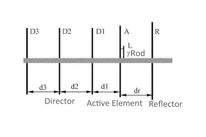
Build a Yagi antenna structure as shown in Figure 1, consists of an active element, a reflector, and a number of directors. Which is slightly longer than the active element reflector to reflect the energy role, and slightly shorter than the active element to guide the role of energy.
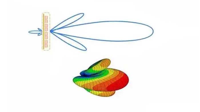
The active element on both sides of the reflector and the director make the original two-way radiation into one-way radiation, in order to improve the gain of the antenna. Yagi antenna has a simple structure, convenient feeding, high gain, widely used in the VHF UHF band.
Antenna size of build a Yagi antenna
Yagi antenna element number, length, and each unit spacing on the antenna gain, front and rear radiation ratio and bandwidth, and other indicators have a great impact.
Build a Yagi antenna size of theoretical calculation is more complex, in most cases is the use of some approximate formula, empirical data for the initial selection, or in a finished antenna on the basis of modification, and then through the experiment, repeatedly adjusted well and then finally determine the relevant data.
Build a Yagi antenna size needs to be determined from the antenna performance indicators in the compromise consideration. The length of the antenna reflector is 35 cm (0.5λ, wavelength λ=70cm), the length of the three leaders is equal, all 31 cm (0.44λ), the length of the active element is 34 cm (0.486λ), and the actual length should be determined in the antenna adjustment.
The spacing of the director is selected with variable spacing and equal spacing two. The unit spacing can be selected between 0.1λ and 0.34. The director’s spacing value is large, the antenna gain is high; spacing is small, and the antenna band characteristics are good.
The antenna lead spacing is 0.2λ. It should be noted that the spacing between the first lead and active element should be smaller, generally 0.14λ. The spacing between the reflector and the active element is also 0.2λ. The length and spacing of each unit of the antenna are shown in Table 1.
| Element | R | A | L | D1 | D2 | D3 | dr | d1 | d2 | d3 |
| Size | 0.5λ | 0.486λ | 0.1λ | 0.44λ | 0.44λ | 0.44λ | 0.2λ | 0.14λ | 0.2λ | 0.2λ |
| CM | 35 | 34 | 7 | 31 | 31 | 31 | 14 | 10 | 14 | 14 |
γ rod matching of build a Yagi antenna
Antenna and feed cable connection is the first to solve the impedance matching problem. The so-called impedance matching is the input impedance of the antenna transformed to the value of the characteristic impedance of the feed line connected to it (generally 50Ω) so that the power output from the radio station will all be able to transmit from the antenna.
Yagi antenna matching method has a variety of forms. Coaxial cable core through the variable capacitor and γ rod connected, cable shield connected to the center of the active element, shorting rod will be active element and γ rod connected and can move.
Adjusting the variable capacitor capacity and shorting rod position can make the antenna match the state. γ match for the unbalanced type can be directly connected with the coaxial cable, which is a very convenient matching way loved by amateur radio enthusiasts.
How to build a Yagi antenna for the 433 MHz?
Build a Yagi antenna production materials required to all the elements are selected Φ3mm copper welding rod, crossbar available 15mm × 15mm, 70cm long square tube, or aluminum alloy material.
First, cut 6 copper rods according to the dimensions in Table 1, and make a good punching mark on the corresponding position of the square tube.
Select a Φ3mm drill bit and use a bench drill to punch through the 5 holes in the square tube so that the copper welding rod can just be inserted into the crossbar.
For easy adjustment and disassembly, drill a hole above the vibrator, weld a nut, and tighten the screw, then the vibrator can be fixed. Note that in square tube drilling the best use table drill, a pistol drill is not easy to control the direction, and easy to causes the vibration tilt.
Find a piece of 60 mm × 15mm, 1mm thick iron sheet, bent at right angles and drilled holes. The long side is fixed on the crossbar, the short side is installed on the BNC connector, and the center of the plug to the vertical distance of the active vibrator is about 20mm.
The iron piece and the square tube between the paint file ensure good contact. Short circuit rods can find two pieces of size 30 mm × 10mm, about 1 ~ 2mm thick aluminum or copper sheet production.
Punch a hole in the middle of the two pieces of aluminum, install the screw, clip on the active element and γ bar, and adjust the spacing of the two copper bars by 20mm, as shown in Figure 2.
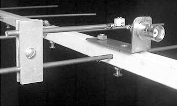
Finally, the porcelain chip capacitor soldered in the core of the BNC connector and γ rod, and the antenna production will be completed.
How to adjust the Yagi antenna?
There are many factors that affect the performance of the Yagi antenna, and the adjustment of the Yagi antenna is more complicated than other antennas. Under amateur conditions, we mainly adjust two parameters of the antenna: resonant frequency and VSWR.
That is, the resonant frequency of the antenna is adjusted near 435MHz, and makes the VSWR of the antenna as close to 1 as possible.
The antenna will be set up from the ground about 1.5m and connected to the standing wave table to start measuring. To reduce the measurement error, connect the antenna to the standing wave table and the radio to the standing wave table cable as short as possible.
The antenna has three places to adjust: the capacity of the trimmer capacitor, the position of the shorting bar, and the length of the active element.
Build a Yagi antenna’s specific adjustment steps are as follows.
(1) Will be fixed in the shorting rod 5 ~ 6cm from the crossbar.
(2) The transmitter frequency to 435MHz, adjust the porcelain capacitor so that the antenna standing wave is minimum.
(3) From 430 to 440MHz, every 2MHz interval, measuring the antenna standing wave, the measured data for the graph or list.
(4) Observe the frequency corresponding to the smallest standing wave (antenna resonant frequency) in the vicinity of 435MHz, if the frequency is high or low, can replace a slightly longer or slightly shorter few millimeters of active oscillator re-measurement of the standing wave.
(5) Slightly change the location of the shorting rod, repeated fine-tuning the porcelain capacitor so that the antenna standing wave in the 435MHz near as small as possible.
Antenna adjustment each time to adjust a place, so easy to find out the law of change. Because of the high working frequency, the magnitude of the adjustment is not too large.
Such as the series connected to the γ bar on the fine-tuning capacitor adjustment capacity is about 3 ~ 4pF, changing a few pico fa (pF) will cause a great change in the standing wave.
In addition, the length of the crossbar, cable position, and many other factors will also have a certain impact on the measurement of standing waves, which is what we need to pay attention to in the adjustment process.
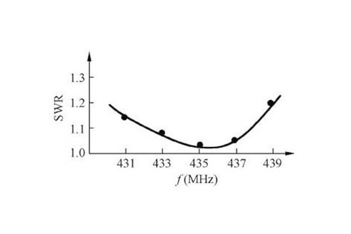
Figure 3 is the measurement result of the standing wave (SWR) after the antenna is adjusted.
Besides this How To Build A Yagi Antenna article, you may also be interested in the below articles.
What Is The Core 5G NR Technology?