Atari Lynx programming tutorial series:
In part 15 we discussed the memory and segments and how those are related. Before we can go into the details of loading segments into memory, we need some background on the cartridges that the Lynx uses for storage of binary information. This part we will look at the internals of cartridges and how to do raw reads from it.
Of ROM and RAM
Before we get started with the internals, it is worth pointing out a few pecularities of the Lynx. In previous parts we touched on this, but now a refresher and some details are badly needed.
You see, the Lynx only has RAM. 64 KB of it. Read part 12 and 15 to find out how this is organized. Other systems have less RAM (sometimes) and use part of their address space to look “into” ROM cartridges. These systems have the luxury of memory mapped swappable ROM. For example, the Atari VCS 2600 only has 128 bytes (!) of RAM, while there is around 4KB of address space to read from ROM “memory” of the inserted cartridge.

Photo: Alex Kidman
No such luck for the Lynx. It only has RAM and will need to read its code and other binaries into RAM from the peripherial device called the cartridge. The cartridge can be viewed as a read-only harddisk of some sort. Like a PC the Lynx will have to read data from the cartridge and store it in memory.
A side note: at one point in time Atari had the idea to read games from tape. There is still reference of the tape and some hardware addresses like MAGRDY0 ($FD84) that are directly related. The timers 1, 3, 5 and 7 were also meant to be used for signalling the baud rate of the tape device.
It might seem that this is sort of limiting and that we took the short straw with the Lynx. Nothing is further from the truth. The setup allows us to use a lot of RAM in any way we like. We are not tied to certain memory ranges that we must use. Additionally, we can have cartridges that are much larger than the available RAM. The Atari Lynx cartridges come in different sizes. The common ones are 128, 256 or 512 KB, although smaller and larger variations can and do exist. We get to choose how and when to load data from the cartridge and where to store it. Heck, you can even stream live from the cartridge as some libraries have already demonstrated. HandyMusic can play sound effects in PCM format straight from the cartridge. How nifty is that?
Physical structure of the cartridge
Even though the sizes vary, all cartridges have something in common: they have the same (maximum) number of 256 blocks. For each cartridge every block contains a fixed number of bytes. Two simple formulas give the total cartridge size from the block size of a cartridge and vice versa:
TOTALSIZE = 256 * BLOCKSIZE – or –
BLOCKSIZE = TOTALSIZE / 256
This tabel helps find the right sizes:
| Cartridge size (KB) | # Blocks | Blocksize (bytes) | Pins |
| 64 | 256 | 256 | A0-A7 |
| 128 | 256 | 512 | A9-A8 |
| 256 | 256 | 1024 | A0-A9 |
| 512 | 256 | 2048 | A0-A10 |
| 1024 | 256 | 4096 | A0-A10+? |
The italic red ones indicate uncommon cartridges. No commercial cartridges with 64 KB and 1 MB have been released during the Atari age.
To give you a visual impression of the cartridges and their sizes, you can take a look at the picture below. It depicts the blocks and their sizes.
No matter how you look at the cartridges, their behavior is always that of a stream of bytes starting somewhere within the cartridge’s binary image and continuing for as long as you are reading bytes.
Close connections of console and cart
The Lynx and the inserted cartridge are connected to each other through a large flat connector that sits inside the Lynx console.
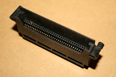
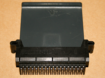
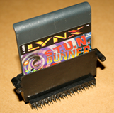
Pictures from http://www.flickr.com/photos/consolingmyself/sets/72157628031292511
The connector passes the pins to a couple of signals and pieces of electronics on the Lynx motherboard:
- VCC +5V
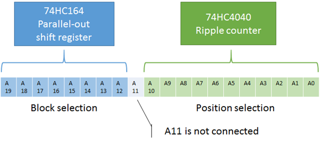
- 74HC4040 (12-stage binary ripple counter; generates cartridge addresses A0-A10)
- 74HC164 (8-bit serial-in, parallel-out shift register; generates cartridge addresses A12-A19)
- Data lines (8-bit lines that go on the data bus)
- Ground
- Auxiliary Data Input/Output (aka AUDIN, not to be confused with Audio IN)
As a programmer you must know about the ripple counter and the shift register. These two pieces of hardware together build the cartridge address you are reading the data from.
It works like this: the shift register builds the high part of the cartridge’s address. It can target 256 different values, that correspond to the 256 blocks (or pages) of the cartridge. The lower part of the address is created from the ripple counter. That counter will start counting at value 0 and auto-increment after every read from the cartridge.
Different sized cartridges have different wirings from the A0 to A20 lines. More precisely, smaller cartridges have not all pins from A0 to A10 connected. They will only wire from A0 up to whatever they need. A 64KB cartridge needs to be able to address 65536 bytes which requires 16 bits. It is sufficient to connect the wires A0 to A7.
Look back at the table above and find out what the pins for each cartridge size are.
The data lines that are present will hold the byte value from the cartridge. Reading it will pulse the CE0/ line on the cartridge, advancing bank 0 to the next byte in the ripple counter. And so on.
The AUDIN pin is used heavily on custom cartridges as follows:
- An extra address line for 1 MB cartridges, giving a virtual A20 line for large enough EEPROMS.
- A bank-switching bit that allows switching between more than one bank (two usually) to increase the maximum number of data in the cartridge to 1 MB as well.
- Enable bit for EEPROM carrying cartridges, such as Lynxman’s Flashcard. By setting this bit high and using special address lines, you can write to the EEPROM, effectively saving (limited amounts of) data to the cartridge. The EEPROM is a separate chip and has around 128-512 bytes of storage.
Shifting and rippling
The block and position selector need to be prepared to read the intended data from the cartridge. Each requires a different approach. The block selection is performed by bit-shifting the right block number into the shift register. The position within the block is prepared by performing strobes, which in turn requires dummy reading, so the ripple counter (automatically) increases to the right position in the block.
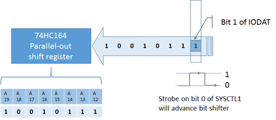
The shift register is like a conveyor belt of bits. You need to place a bit on the belt, advance the belt one position and place the next bit. After performing this 8 times you are certain to have the right block selected. There are two registers involved in performing this bit shifting: $FD8B (IODAT) and $FD87 (SYSCTL1).
IODAT is a hardware register that has a bit for the data to be placed into the shift register. Bit 1 of this address is the Cart Address Data output bit. IODAT is a weird register, in that it can be read from and written to, but the individual bits provide either input or output access, so will only make sense when used appropriately You can control what direction (input or output) it has by setting it in the IODIR ($FD8A) register. It is sort of similar to the way the MAPCTL register determines whether to use RAM or hardware registers based on the bits you set. You need to set the direction for bit 1 of IODAT to 1 for output. After that, by setting that same bit 1 of IODAT you determine what is the next bit on the shift register for the cartridge address. The shift register is advanced by strobing bit 0 (called CartAddressStrobe) of SYSCTL1. A strobe means that the value of the bit changes from 0 to 1 and back to zero again. Although the shifter will except the data at the rise of the strobe bit, it must be set back to 0, as the high level of the bit is used to reset the ripple counter.
Here’s the general flow:
- Turn on cartridge power
- Set directions on IODIR
- Set bit 1 of IODAT to value of current address part (in order from A19 to A12)
- Strobe bit 0 of SYSCTL1 (write 1 then 0, assuming you start with a zero value)
- Repeat from 3 until all 8 bits have been set.
In assembler code this looks like the following:
lynxblock:
	pha
	phx
	phy
	lda __iodat
	and #$fc
	tay
	ora #2
	tax
	lda _FileCurrBlock
	inc _FileCurrBlock
	sec
	bra @2
@0:	bcc @1
	stx IODAT
	clc
@1:	inx
	stx SYSCTL1
	dex
@2:	stx SYSCTL1
	rol
	sty IODAT
	bne @0
	lda __iodat
	sta IODAT
	stz _FileBlockByte
	lda #<($100-(>__BLOCKSIZE__))
	sta _FileBlockByte+1
	ply
	plx
	pla
The code above is from the CC65 implementation for selecting a block, actually. It shows a couple of things when we forget about the details and the optimizations.
- Notice the two calls to SYSCTL1 for strobing bit 0 to advance the shift register.
- The accumulator holds the block number to select. The rotation of the accumulator is moving the next (highest) bit in the carry flag. The first call to IODAT stores the value 1 in the CartAddressData bit, if that carry flag was set. The second call is used to always put a 0 in as the default, allowing the first call to be skipped for a zero bit.
- At the end of the routine the remaing number of bytes in the block is set. We need this to determine the block edge transitions later on.
- The __iodat value is used to get the current value of the IODAT register. Two shadow variables are declared to hold the values that where written to the registers IODAT and IODIR, conveniently called __iodat and __iodir (with double underscores). The shadow values are needed, because we can never read the values back from the registers, but might want to inspect them later on.
For completeness sake it is worth mentioning that in the startup code of any CC65 compiled program the IODAT and IODIR get initialized. They are set to $1B and $1A respectively. You can find the fragment for the shadow variables in crt0.s:
ldx     #$1b
stx     __iodat
dex;  $1A
stx     __iodir
The initialization of the actual registers IODAT and IODIR is done using a longer list of initialization values for Mikey. This is also in crt0.s (around line 40):
MikeyInitReg:  .byte $00, …, $50, $8a, $8b, $8c, $92, $93
MikeyInitData: .byte $9e, …, $ff, $1a, $1b, $04, $0d, $29
After having prepared the shift register it is a matter of reading data from the $FCB2 (RCART0) address. The $FCB3 (RCART1) address is used for reading from the second bank that might be present. Usually there is only one bank (bank0) on a cartridge. When reading from RCART0 the strobe CART0/ is used and it will advance the ripple counter to the next value, essentially autoincrementing the cart’s current address.
Reading from cartridges
Let’s assume that the data we want to read from the cartridge is located somewhere like this:
The picture shows the data starting in the middle of the second block and continuing into the fifthblock. The way to read this data is to advance the high part of the cart address to the second block, then dummy read until the starting point of the data is reached. A thing to remember is that the blocks have a certain size. This is relevant for two reasons.
- You need it in calculations of the desired block if all you have is the consecutive byte number. The ripple counter is automatically set to zero by changing the high part of the cartridge address (because this requires using the strobe for the bit shifter which resets the counter). This also means that you need to do the correct number of dummy reads, also determined by the blocksize.
- When crossing the boundary of a block you need to increase the block number to read the right data. If you do not do that, you will read data from the same block again. That’s why you need to keep track of how many bytes are left in the current block. When it reaches zero you must increase the block number by shifting in 8 bits again.
We could do this using assembler, but that has been done. There is also a higher level abstraction from C. The methods lseek and read will do what we want, …. sort of. This is what the functions look like (from the unistd.h include file):
int __fastcall__ read(int fd, void* buf, unsigned count);
off_t __fastcall__ lseek(int fd, off_t offset, int whence);
The lseek method takes three parameters, of which only one is relevant. The file descriptor fd is always 1 for the Lynx, and for whence only SEEK_SET is supported. That leaves the offset you want to have into the cartridge. The offset is passed using a type off_t, but it is in fact an long integer that can hold the large zero-based offset from the beginning of the cartridge. In a 2MB cartridge this might actually be 2^21-1 = 2097151.
lseek will set the shift register to the correct value and advance the ripple counter to the start of your data, both depending on your block size. It supports the 512, 1024 and 2048 byte block sizes.
off_t offset = 0;
lseek(1, offset, SEEK_SET);
You might need to calculate the offset from the block number and offset in the block. That’s kind of silly, because the lseek implementation does the reverse. It’s just the way lseek is defined.
You need to include the headers stdio.h (for SEEK_SET constant), unistd.h (for the function prototypes of lseek and read) and sys\types.h (for the off_t type).
The actual reading is performed by calling read.
unsigned char buffer[256];
read(1, &buffer, 256);
You need to have a buffer that is going to hold the data read from the cartridge. The example above shows a 256 byte buffer and reads a 256 bytes sized chunk from the cartridge into it.
Here is an example of how to read the contents of your cartridge and dump it to the screen in multiple pages:
void dump_cartridge()
{
  off_t offset = 0;
  unsigned char buffer[80];
  unsigned char byte;
  char text[4];
  unsigned char page = 0, index = 0, x = 0, y = 0;


  // Advance current address to start of cartridge
  lseek(1, offset, SEEK_SET);

  do
  {
    // Read 80 bytes for one page into buffer
    read(1, &buffer, 80);
    index = 0;
    tgi_clear();

    // Draw all values
    for (y = 0; y < 10; y++)
    {
      for (x = 0; x < 8; x++)
      {
        itoa(buffer[index++], text, 16);
        tgi_outtextxy(x * 20, y * 10, text);
      }
    }
    tgi_updatedisplay();
    wait_joystick();
  }
  while (++page < 3);
}
This example uses a loop that will read 80 bytes for a page into the buffer, then display them in hexadecimal value 8 byte per line for a total of 10 lines. Pressing any normal button on the Lynx advances the current page.
You should try this: open the LNX file using the Binary Editor (right-click your tutorial-cartridge.lnx file, then select Open With…) and compare the contents you see with what is displayed. Mind you, you have to skip 64 bytes of the LNX files. We’ll explain later why that is.
The example is included in the sample source code. It can easily be expanded to allow you to select the current block number and start from there.
Next time
This part showed how the cartridge system works at a low level and with the CC65 methods lseek and read. The Lynx cartridge can also use a simple file system with a directory and file entries. The next part will we look at how files can be read, and how this relates to the segments we saw in memory segments. Till then.





Thanks for these tutorials. They help me a lot, although they are pretty deep to my understanding yet. But in the near future I will use them a lot . Just one observation: your last few tutorials are not visible from the tutorials main menu, they are kind of hard to find.
Thanks for the comment. I’ve been reworking the website, so I hope things are a little better now. Please let me know if they are not.
The atari lynx sadly only has ram to work with,but bankswitching has the magic of overcome the limmited 64KB space by swapping to another section of 64 KB rom space etc,,, like when you exciting to another world, so you theoritically be allowed to make games as big as you want, aslong each section id withing the 64KB space.
This technic can be great for animations wich should be in a cluster chain format, to read,load & exicute one section of data an after another to overcome space limitations.
The Lynx doesn’t do memory-mapping to ROM cartridges, so bankswitching is not supported/relevant. The only bankswitching that is done is via the AUDIN pin to create a bigger cartridge by selecting 1 out of 2 chips, or using the AUDIN as an additional address line. Even so, all cartridges must be read to RAM before their contents can be used.
Well if the lynx has to load data first into ram before it can be used, then how can it do that as it has 64KB of work ram, you never fit 128,256 or 512KB rom into that 64KB of ram ,unless the lynx has 2 256 KB. Of load ram to rip the entire rom into it before it can be used,i readed somewhere that the lynx contains 2 chips of 256KB of ram but not on wikipedia,but still am not sure about that.
Thanks for responding.